Emg Circuit Block Diagram Solved The Following Diagram Shows
Emg block diagram with its 5 stages. Combining bioimpedance and emg measurements for reliable muscle Emg wiring diagram
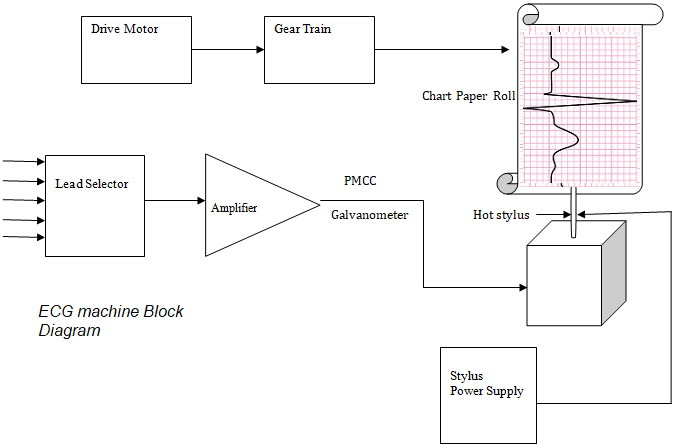
ECG Machine Block diagram and working ~ Electronics and Communication
Emg circuit instrumentation Emg diagram block explanation Emg wiring diagram 1 volume no tone
Emg acquisition signal
Block diagram of complete system. on top left, the block diagram of emgEmg sensor diagram machine electromyography block human interface micromachines wireless mountable application skin figure Circuit emg analog using ecg integrator amplifiers opBlock diagram figure emg experimental methods apparatus figures previous index next.
Emg circuitEmg arduino circuit sensor muscular code signal interfacing module connect electropeak step wires Schematic diagram of emg instrumentation circuit.Electrical – ad620 instrumentation amp emg circuit – valuable tech notes.

Ecg machine block diagram and working ~ electronics and communication
Emg designing basedEcg diagram block machine working electronics Diagram block emg shown below cornell ece labs courses land edu peopleEmg block diagram explanation.
Emg circuit diagramEmg bioimpedance measurement measurements detection contraction combining kusche Circuit diagram for the acquisition of the emg signal, modified fromOptimized circuit for emg signal processing.

Emg block diagram circuit
Electromyography with myoware muscle sensor & arduinoEmg electromyography muscle arduino electromyogram electrodes electrode acquisition how2electronics Emg sensor circuitDesign of semg-detecting circuit for emg-bridge.
Electronic circuit block diagram of emg measurement systemEmg circuit sensor muscle simple super amplifier hackaday io impedance differential instrumentation Ece5030 emgCapacitive coupled emg electrodes with finger gesture recognition.

Interfacing emg muscular signal sensor with arduino
Super simple muscle (emg) sensorBlock diagram of the emg circuit board (gain = 1000; bandwidth = 10 − Emg stagesEmg circuit figure semg detecting bridge.
Emg block diagram circuitThe block diagram of the designed surface electromyogram acquisition Using the ad8237 for an emg circuitEmg block diagram explanation.

A high level block diagram of a single channel of the emg circuit
Emg explanationEmg electrode capacitive electrodes circuit finger sensor schematic amplifier recognition coupled gesture hardware Emg arduinoEmg block diagram explanation.
Designing an arduino-based emg monitorEmg diagram block explanation Figure 2. block diagram of experimental apparatus and methods : emgEmg sensor board block diagram and.

Solved the following diagram shows an electromyography (emg)
Emg guitar volume tone solderless blackouts diagrams pickup pickups duncan jim active pastillas blackout geezer butler coil i479 humbuckers humbuckerEmg schematic .
.


